Ceramic Capacitor Mtbf

Are There Any Methods For Estimating The Lifetime Of A Capacitor Murata Manufacturing Co Ltd

What Are The Failure Period Faq Tdk Product Center
Https Www Bqr Digital Com Bqrpc Examples Examplereport1 Pdf

What Is Mtbf Mean Time Between Failures Faq Tdk Product Center
Free Mtbf Calculator User Guide
Solved Answer All The Following Questions A Manufacturer Chegg Com

Tdk calculates fit from the results of high temperature load testing based on jis c 5003 standards.
Ceramic capacitor mtbf. Capacitor mtbf mil hdbk 217 rev. The duration period can be estimated by determining voltage acceleration constant 1 and activation energy 2. For 70 capacitors in the circuit the mtbf of all of them combine has dropped significantly. What factors affect the expected life and failure rates of mlccs.
Typical accelerated test for ceramic capacitor is an accelerated test using temperature and voltage factors. There have been many reports until now describing that acceleration equation for ceramic capacitor conforms to eyring model. Answer to faq on fit values and mttf mtbf for tdk s multilayer ceramic chip capacitors mlccs. Measuring the number of failures over time provides a failure rate λ.
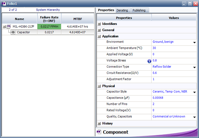
A summary of specifications are shown in table 1. Mtbf we use load life rating. Tdk uses the arrhenius model revised by prokopowicz and vaskas to describe failure caused by systematic degradation. F notice 2 learn about environmental test chambers to calculate the mtbf and failure rate of a capacitor using the mil hdbk 217f failure model enter its parameters in the following table.
This means that 100 greater than 99 999 calculated to be more than 10 9 s reliable of capacitors are expected to successfully operate over a 10 hour per day 10 year operating life. For the dc buss capacitor the expected reliability at 10 years of life 36 500 hours is. The part number for the example is c0805c104k1rac. In this example we will calculate a fit for a commercial grade ceramic capacitor.
The mean time between failure mtbf or for components the mean time to failure mttf is the distribution for. To find the mtbf you would do the following calculations. Most capacitors are considered a failure when the capacitance has changed by 20 to 25 of its initial value. In regard to the previous example mtbf would equal 4140 9 years.
All of these capacitors have a fit number of 16 5 same as previous example. This model assumes that the degradation of the dielectric of the capacitor depends both on the temperature and. In aluminum electrolytic capacitors as they are used the capacitors slowly degrade over time and once a capacitor has degraded beyond a specified amount the capacitor is considered to be a failure. 0 0008658008658 x 10 9 865 800 hours.
Changes in applied voltage and temperature will have an effect on the lifetime of individual components. Fit and mttf mtbf 6. At 20 years this drops to 6 9 s reliable. For the specific vishay tantalum capacitors contained within the program the program s unique characteristics enable instantaneous results and provide important design related information.
According to this formula the average failure time increases when the failure rate decreases. Application note failure in time. The failure rates are listed as fit failures in time and mtbf mean time between failures.
Https Ec Kemet Com Wp Content Uploads Sites 4 2019 10 An1002 0715 Calculating Failure In Time Pdf

Ceramic Capacitor Murata Manufacturing Co Ltd

Wp Calculating Failure In Time Fit For Ceramic And Tantalum Capacitors Engineering Center

Ceramic Capacitor Reliability Data Request Venkel

Ceramic Capacitor 101 100pf Ceramic Capacitor Sigmatechbd
Http Catalogs Avx Com Advancedceramiccapacitors Pdf

How Hot Is Too Hot
The Basics Benefits Of Tantalum Ceramic Capacitors Passive Components Blog

Lighting For Life Digikey

Ceramic Capacitor Capacitors Ceramics Ceramic Materials
Mil 217 Bellcore Telcordia And Other Reliability Prediction Methods For Electronic Products Reliasoft

Reliability In Solar Inverter Design

Ceramic Capacitor 220 22pf Techshopbd Ceramic Capacitor 220 22pf Sigmatechbd Sigmatechbd

