Ceramic Cartridge Preamp Circuit

Ceramic Cartridge Preamp Circuit Pete S Mosfet Preamp

Ceramic Cartridge Preamp Circuit The Revitalizer

Ceramic Cartridge Phono Pre Amp Page 1 Phono Stages Step Ups Lenco Heaven Turntable Forum

Ceramic Cartridge Preamplifier Circuit Layout

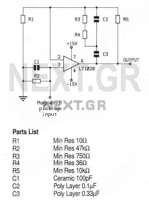
Preamp Equalization Network
Riaa Phono Preamplifier Using Lf353n

I would therefore conclude that unless the line input of an amplifier is of high impedance then when using a ceramic cartridge into this line input my phono pre amp will be of benefit.
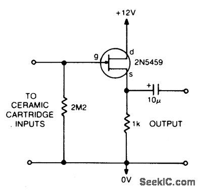
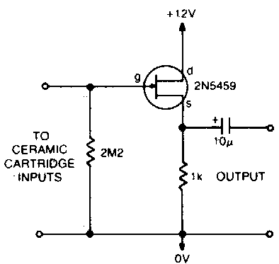
Ceramic cartridge preamp circuit. Simple preamplifier circuit duration. It can run from a battery supply of 9v. Ceramic cartridges of capacitance 800 pf to 12 000 pf with output voltages up to 900 mv can be connected making it a very versatile. These inputs have no riaa eq ceramic pickups are amplitude sensitive and the riaa curve produces very roughly a constant amplitude cut.
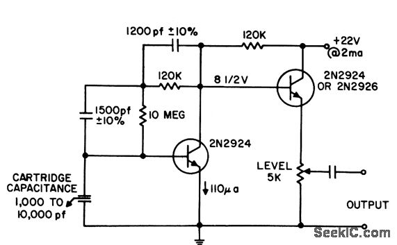
The third diagram for a ceramic cartridge which is transistorized i copied it from our stereo radiowealth clair de lune. These two circuits have been requested for a violin pickup but could equally well suit a ceramic or crystal pickup. As shown above the circuit is actually designed for crystal microphones or ceramic cartridges. This ceramic cartridge preamplifier circuit requires the least number of components and produces highest quality sound with wonderful bass.
Buffering low output mm moving magnet pickups. Circuit digest 9 615 views. 2 using an fet. Dc negative feedback keeps the operating level stable.
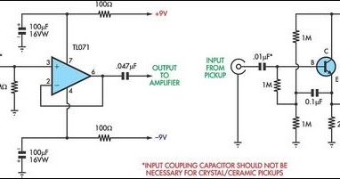
Similarly violin pick ups made by fishman barcus berry and others are piezo devices. Ceramic cartridge preamp circuit the revitalizer. Riaa and buffer preamp for vinyl record players versatile preamp for mm pickups and ceramic crystal pickups. The op amp circuit uses a tl071 connected as a voltage follower.
The independent 1 5 v preamplifier circuit explained below is made up of individual amplifying transistor preceding an emitter follower. In this ceramic cartridge preamp circuit we are able to set the precise equalization required for any cartridge by calculating the required value of r1 from the cartridge capacitance. A level of about 0 1 volt should be fine for those. My ceramic phono pre amp circuit would therefore correctly match the line input impedance typically 100k of these modern day valve amplifiers.

Preamp Stage For Ceramic Phono Cartridge Or Violin Pickups Eeweb

Preamplifier For Ceramic Pickup Preamplifier Circuits

Antique Radio Forums View Topic Preamp For Ceramic Cartridge

Simple Schematic For Using Ceramic Cartridges On Mm Phono Preamp Audiokarma Home Audio Stereo Discussion Forums
Preamp Stage For Ceramic Phono Cartridge Or Violin Pickups Circuits Projects
Using A Ceramic Cartridge With Modern Electronics Uk Vintage Radio Repair And Restoration Discussion Forum
Ceramic Cartridge Equalization
Velocity Response Phono Preamp Audio Circuit Circuit Diagram Seekic Com
Some Useful Audio Circuits
Preamplifier And High To Low Impedance Converter Amplifier Circuit Circuit Diagram Seekic Com
Audio Preamplifiers Circuits Audio Circuits Next Gr

Disc And Adamantine
Preamplifier And High To Low Impedance Converter Circuit Diagram Circuits Diagram Lab

