Ceramic Resonator Clock Circuit

Crystal Vs Ceramic Resonator And Oscillator Circuit In 2020 Electronics Basics Circuit Electronics Circuit

Crystal Oscillator Vs Resonator Real Time Clock Crystals What Are Crystals

Quartz Crystal Oscillator Electronic Engineering Crystals Electronics Components

Understanding An Inductor And It S Working In 2020 Inductors Dc Circuit Current Source

16 Mhz Ceramic Resonator Oscillator Capacitors Ceramics Microcontrollers

Hartley Oscillator Circuit Design Electronics Circuit Circuit

The design of the circuit varies with the application and the ic to be used etc.
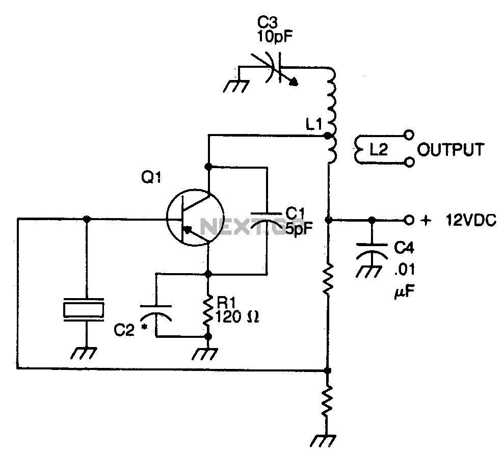
Ceramic resonator clock circuit. Power up the circuit with a clean 3 v to 5 v dc supply i e with a single li ion battery is. A ceramic resonator is often used in place of quartz crystals as a reference clock or signal generator in electronic circuitry due to its low cost and smaller size. In a ceramic resonator oscillator the inductor is replaced by a ceramic resonator taking advantage of the fact that the resonator becomes inductive between resonant and anti resonant frequencies. Also what kind of osciallator circuits.
The material can have two or more electrode which when connected to an oscillator circuit gets mechanical vibration as a result an oscillating signal of a specific frequency is generated. They cost less and so are used where stability isn t as important. This may not be important for a microprocessor but will be important if the circuit is used in a radio a clock or other timing critical applications. Crystal is the common term used in electronics for the frequency determining component a wafer of quartz crystal or ceramic with electrodes connected to it.
Although the basic configuration of the circuit is the same as that of a crystal controlled oscillator the difference in mechanical q results from a difference in circuit constants. That s all you need to make this shortwave transmitter circuit. They do not hold their frequency as well. Resonators are made from ceramic elements rather than quartz.
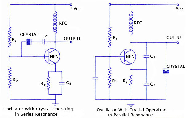
5 discount for the first 40 to order on jlcpcb with code jlcpcbnoob learn how crystal and ceramic resonators work. The operating principle of these oscillation circuits can be seen in fig 2 1. The operating principle of these oscillation circuits can be seen in fig 2 1. A crystal oscillator is an electronic oscillator circuit that uses a piezoelectric resonator a crystal as its frequency determining element.
The most commonly used circuit is the colpitts circuit. The lower q and higher frequency range achievable can be beneficial in use of tcxos temperature compensated crystal oscillators. The most commonly used circuit is the colpitts circuit. For stable operation in such a design the phase shift compensation and gain control are provided by additional capacitors and resistors.
You can also replace the 10 7 mhz ceramic resonator with any other between 2 3 mhz to 26 mhz range. In a ceramic resonator oscillator the inductor is replaced by a ceramic resonator taking advantage of the fact that the resonator becomes inductive between resonant and anti resonant frequencies.

Crystal Oscillator Vs Resonator Electronics Basics Electronics Projects For Beginners Crystals

Crystal Oscillator Vs Resonator In 2020 Crystals Electronics Circuit What Are Crystals

Oscillator Circuit Design Ecs Inc International
100khz Crystal Oscillator

Ceramic Resonator Youtube

Pin On Electronic Circuits

68 Odnoklassniki Elektronnaya Shema Principialnaya Shema Radiolyubitel
Crystal Oscillator Circuit Oscillator Circuits Next Gr

Circuit For Calibration Of An Ammeter In 2020 Ohms Law Voltage Divider Circuit Diagram

Thyristor Commutation Techniques Techniques Tutorial Electronics Projects

Ceramic Resonator Ceramics Utensil Spatula
Overview Of Crystal Oscillator Circuit Working With Applications

Circuit Connected To A Capacitor Mathematical Expression Equations Electric Flux

